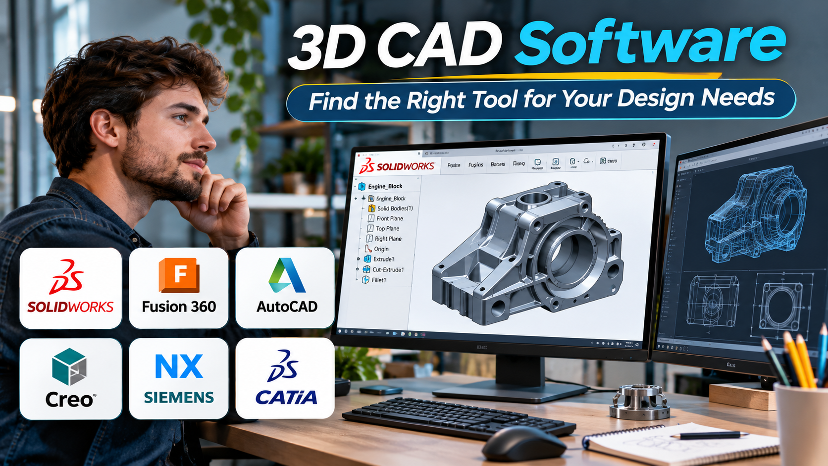
A small change to a product design can cause big problems later. A hole may be too close to an edge. Two parts may not fit together. A component may be too large for the machine that will produce it.
Good 3D CAD software helps teams find these problems before production begins.
But not every CAD tool works in the same way.
Some applications focus on mechanical parts and assemblies. Others support large engineering projects, cloud collaboration, or quick 3D printing. The right choice depends on what you design, how your team works, and what happens after the model is finished.
For example, a student designing a phone stand has different needs from an automotive engineer working on a complex assembly. A small workshop may need simple drawings and reliable file exports. A large manufacturer may need strict version control and links to its production systems.
This guide compares established 3D CAD tools. It also explains the features, costs, and workflow choices that matter most.
Why the Type of CAD Software Matters
CAD stands for computer-aided design. It allows users to create, edit, and study digital designs.
3D CAD software adds depth to those designs. Users can build solid objects, view them from different angles, and check how parts fit together.
A typical mechanical design process includes:
- Sketching: Drawing basic shapes and setting dimensions.
- 3D modeling: Turning sketches into solid parts.
- Assembly design: Combining parts into a complete product.
- Design checks: Looking for fit, clearance, or strength problems.
- Technical drawings: Adding dimensions and notes for manufacturing.
- Export: Preparing files for machining, 3D printing, or other systems.
Not every project needs all these steps.
A hobbyist may only need a printable model. A manufacturing company may need detailed drawings, material data, and approval records.
The first step is to understand which type of CAD workflow fits your project.
Parametric CAD
Parametric CAD uses dimensions, rules, and relationships to control a model.
Imagine a metal bracket with four mounting holes. If its width changes, the software can update the hole positions based on the rules you created.
This approach is useful for products that need regular changes.
Direct modeling
Direct modeling lets users change geometry by moving, pushing, or pulling faces.
It can be useful for quick edits and imported models that lack an editable design history.
However, direct edits may not preserve the same design intent as a well-built parametric model.
Surface modeling
Surface modeling focuses on creating and controlling complex shapes.
It is useful for products such as car bodies, consumer electronics, and curved plastic parts.
Some CAD tools combine solid, surface, and direct modeling in one application.
Comparing the Main 3D CAD Software Options
The tools below serve different users and design needs. They are grouped by practical strengths rather than a numbered ranking.
| Software | Main strength | Suitable for | Key consideration |
|---|---|---|---|
| SOLIDWORKS | Parametric mechanical design | Product engineers and manufacturers | Commercial licensing and desktop requirements |
| Autodesk Fusion | Integrated CAD and manufacturing tools | Small teams, product designers, and workshops | Cloud services and plan limits |
| PTC Creo | Advanced parametric engineering | Industrial product development | Training and setup needs |
| Siemens NX | Complex product engineering | Large manufacturing teams | Cost and system complexity |
| CATIA | Complex shapes and large product programs | Automotive and aerospace engineering | Specialist skills and platform requirements |
| Onshape | Cloud-based CAD and teamwork | Distributed design teams | Internet access and plan conditions |
| FreeCAD | Open-source parametric modeling | Makers, students, and technical users | Workflow and compatibility checks |
| Shapr3D | Direct and parametric design workflows | Product designers and early-stage design | Feature and export limits by plan |
| AutoCAD | Technical drafting and 3D design | Teams that rely on DWG drawings | Not a direct replacement for full mechanical CAD systems |
SOLIDWORKS: A Strong Choice for Mechanical Product Design
SOLIDWORKS is widely used for mechanical design. It supports parts, assemblies, and detailed engineering drawings.
Its main strength is parametric modeling. Designers can build parts using sketches, dimensions, and features. These features form a design history that can be edited later.
For example, an engineer can create a machine housing with mounting holes, internal supports, and a removable cover.
If the housing changes size, related features can update based on their design rules.
Why teams choose SOLIDWORKS
The software supports many tasks found in mechanical engineering:
- Part and assembly modeling
- Sheet metal design
- Weldment design
- Technical drawings
- Design checks and motion studies
- Simulation through supported products and licenses
SOLIDWORKS also has an established network of partners, training providers, and third-party tools.
This can help teams that need support or work with suppliers using the same software.
Where it may be less suitable
Traditional SOLIDWORKS desktop CAD is Windows-focused.
Licensing, support, and extra tools can also increase costs. Teams should check which features are included in their chosen package.
SOLIDWORKS is a sensible option for companies that need detailed mechanical designs and controlled drawings.
It may be more software than a beginner needs for simple 3D printing projects.
Autodesk Fusion: Connecting Design with Manufacturing
Autodesk Fusion brings several product development tasks into one environment.
It combines CAD with computer-aided manufacturing (CAM), electronics design, and other engineering tools.
This makes it attractive to teams that want to move from a digital model to a physical product.
A practical example
Imagine a small company developing an aluminum camera mount.
The team first creates a 3D model. It then checks the fit of the parts and prepares the design for CNC machining.
Fusion can support both the design and machining stages. This can reduce the need to move between separate applications.
Its tools also support collaboration and project data management.
What to check before choosing Fusion
Fusion uses cloud-connected services, although some work can be done offline.
Teams should understand how files are stored, shared, and accessed when internet service is unavailable.
Autodesk also offers different license types and extensions. Some advanced functions may require extra payment.
Fusion is worth considering for product development teams that need both design and manufacturing tools.
PTC Creo: Engineering Products That Change Often
PTC Creo is designed for detailed product engineering.
It is particularly useful when products contain many related parts and need regular updates.
Creo supports parametric modeling, assemblies, drawings, and advanced engineering workflows.
Its capabilities can also extend to simulation, manufacturing, and other tasks through specific products or extensions.
Where Creo stands out
A key strength is its focus on design intent.
Design intent means building a model so that changes follow planned rules.
Consider a family of industrial pumps. Each pump may have a different size, but many parts follow the same design rules.
A parametric system can help engineers manage these changes without rebuilding each design.
Creo also offers tools for complex geometry and model-based engineering.
The main trade-off
Creo has a broad set of features. Learning and managing them can take time.
Smaller teams may not need its full range of engineering functions.
Before buying, companies should test the tools they will use most. They should also confirm which extensions are required.
Siemens NX: Managing Complex Engineering Work
Siemens NX is a high-end engineering platform.
It supports advanced CAD, CAM, and CAE workflows. CAE means computer-aided engineering. It includes tools used to study how a design may perform.
NX is often considered for complex products and large manufacturing programs.
Why large teams use NX
A major product may contain thousands of parts.
Each part may have its own design, material, supplier, and production requirements.
NX supports detailed modeling and assembly work. It can also form part of a wider Siemens engineering environment.
For example, a manufacturer may connect NX with Teamcenter to manage product data, revisions, and approval processes.
This can help teams work with shared product information.
What makes NX demanding
NX can require significant spending on licenses, training, and system setup.
It also needs careful planning when used across large teams.
A small business making simple parts may find a lighter CAD tool easier to manage.
NX makes more sense when product complexity and engineering needs justify the investment.
CATIA: Designing Complex Products and Surfaces
CATIA, developed by Dassault Systèmes, is used for advanced product design and engineering.
It is especially relevant to industries where shape, fit, and product complexity matter.
These include automotive and aerospace engineering.
Why CATIA is different
CATIA offers tools for detailed surface design, solid modeling, and large product assemblies.
For example, designing a car body involves more than creating an attractive shape.
Engineers must consider how panels connect, how parts fit, and how the final design can be made.
CATIA supports this type of work through its advanced modeling tools.
It also connects with broader product development systems, depending on the chosen CATIA product and platform.
What to consider
CATIA includes different products and licensing options. Features can vary between them.
Teams should confirm which modeling, collaboration, and data management tools they need.
CATIA may be excessive for simple mechanical parts or small 3D printing projects.
It is most useful when complex surfaces and detailed product engineering are central to the work.
Onshape: Cloud CAD for Teams Working Together
Onshape takes a different approach to CAD.
Instead of relying on a traditional file-based desktop workflow, it provides a cloud-native design environment.
Users can work through a web browser or supported mobile applications.
Why collaboration is its main strength
Imagine three engineers working on the same product from different locations.
One designs the housing. Another works on the mounting system. The third reviews the assembly.
In a traditional workflow, teams may need to exchange files and manage separate copies.
Onshape stores design data in a shared cloud environment. It includes version history and branching tools.
These features help teams track changes and work on related designs.
Important limits
Cloud-based CAD depends on reliable access to online services.
Companies should review data security, access controls, and their requirements for offline work.
They should also check plan conditions. For example, the visibility of documents and access to private projects can depend on the subscription.
Onshape is worth evaluating when teamwork and version control are major priorities.
FreeCAD: Open-Source CAD Without License Fees
FreeCAD is a free, open-source 3D modeling application.
It supports parametric design and runs on Windows, macOS, and Linux.
Users can create sketches, solid parts, assemblies, and technical drawings.
FreeCAD also provides tools for other engineering tasks through its workbenches.
Why FreeCAD is useful
FreeCAD gives users access to technical modeling tools without commercial license fees.
This makes it appealing to students, hobbyists, independent engineers, and small businesses.
Its open-source design also allows users to inspect and change the software.
Python scripting supports automation and custom workflows.
FreeCAD can exchange files through formats such as STEP, IGES, and STL. This helps users work with other CAD and manufacturing tools.
Where extra care is needed
FreeCAD’s interface and workflows may take time to learn.
Users moving from commercial CAD systems should test assembly behavior, drawing tools, and imported models.
It is also important to check whether the required workbench supports the intended task.
FreeCAD is a practical option when cost control and open-source access matter more than a specific commercial software ecosystem.
Shapr3D: Fast Modeling Across Different Devices
Shapr3D focuses on making 3D modeling accessible across supported devices.
It offers CAD workflows on Windows, macOS, and iPadOS.
Its design tools support both direct modeling and history-based editing.
This makes it useful for creating early product ideas and refining them into detailed models.
Where Shapr3D fits
A product designer may start with a rough concept on an iPad.
The designer can then adjust dimensions, edit solid geometry, and prepare the model for further work.
Shapr3D supports formats used in engineering and manufacturing, including STEP and other formats depending on the plan.
Its interface is designed around direct interaction with models.
The trade-off
Shapr3D offers different subscription levels.
The free option has limits on projects and exports. Paid plans provide additional features.
Teams should confirm support for their required file formats, technical drawings, and collaboration needs.
Shapr3D is attractive for designers who value flexible devices and fast modeling.
It should still be tested against the needs of detailed engineering projects.
AutoCAD: When Drawings Matter as Much as 3D Models
AutoCAD is best known for technical drafting.
It supports both 2D drawing and 3D design, but its role differs from full mechanical product development systems.
Many teams use AutoCAD to create and maintain technical drawings.
These may include layouts, equipment plans, and manufacturing details.
Why AutoCAD remains relevant
The DWG format is common in many design workflows.
Companies with large drawing libraries may need reliable tools to edit and share these files.
AutoCAD provides drawing, annotation, layer management, and automation features.
It also supports 3D solids and surfaces.
Where another tool may be better
AutoCAD does not offer the same integrated, history-based mechanical assembly workflow as products such as SOLIDWORKS or Creo.
For complex mechanical products, a dedicated parametric CAD system may be a better fit.
AutoCAD makes sense when detailed drawings and DWG-based workflows are the main requirements.
File Compatibility Can Make or Break a CAD Project
A CAD model is useful only if the next person or system can work with it.
This is why file compatibility deserves careful attention.
Different formats carry different types of information.
| File format | Common use | What to check |
|---|---|---|
| STEP | Sharing solid geometry between CAD systems | Whether geometry and assembly structure transfer correctly |
| IGES | Exchanging surfaces and geometry | Whether imported surfaces need repair |
| STL | 3D printing and mesh-based workflows | Mesh quality and correct scale |
| 3MF | Sharing 3D printing data | Printer and software support |
| DWG | Technical drawings | Layers, dimensions, and drawing accuracy |
| DXF | Drawing and cutting workflows | Units and supported drawing elements |
| Native CAD files | Editing models in their original software | Software version and license compatibility |
A file that opens successfully may still have problems.
For example, a STEP file may preserve the shape of a part but not its original feature history.
This means another engineer can see and edit the geometry, but may not be able to change the original sketches and design rules.
A good compatibility test should include both import and export.
Open the model in the target software. Check its dimensions, units, geometry, and assembly structure.
Then make a small change and save it again.
This helps reveal problems before they affect a real project.
CAD Software and Manufacturing: Check the Full Workflow
Creating a good 3D model is only part of product development.
The design must also be suitable for manufacturing.
Different production methods have different needs.
CNC machining
CNC machining removes material from a workpiece.
The CAD model helps define the required shape.
CAM software then creates toolpaths that guide the machine.
Autodesk Fusion and Siemens NX offer integrated CAD/CAM workflows. Other CAD tools may connect to separate CAM applications.
Teams should check support for their machines, cutting operations, and post-processors.
3D printing
For 3D printing, the CAD model is often exported as STL or 3MF.
A slicer then prepares the model for printing.
The CAD tool does not replace the need to check wall thickness, clearances, and print orientation.
Sheet metal production
Sheet metal parts often need bends, holes, and flat patterns.
A suitable CAD system should support the required bend rules and manufacturing drawings.
Tools such as SOLIDWORKS and Creo provide dedicated sheet metal capabilities.
The right choice depends on the parts being made and the manufacturing process.
The Costs That Are Easy to Miss
The purchase price is not the full cost of CAD software.
A team may also spend money on training, hardware, file conversion, and support.
| Cost area | Why it matters |
|---|---|
| Software license | May be a subscription or another commercial arrangement |
| Extra modules | Simulation, CAM, and data management may cost more |
| Hardware | Large models may need more memory and graphics power |
| Training | Engineers need time to learn the workflow |
| File migration | Existing models may require conversion or rebuilding |
| Support | Technical help may be included or sold separately |
| Data management | Teams may need version control and access rules |
| Integration | CAD may need to connect with manufacturing and business systems |
Free software can reduce license costs. It does not remove the need for training and support.
Commercial software can also be good value when it fits an existing workflow.
The best cost comparison looks at the full design process.
A Practical Test Before Choosing CAD Software
Software demonstrations often show clean models and smooth workflows.
Real engineering projects are rarely that simple.
A useful test should include a design that reflects your actual work.
For example, create a small mechanical assembly with several parts.
Then complete these steps:
- Create the parts using dimensions and design rules.
- Combine them into an assembly.
- Change the size of one important part.
- Check whether related parts update correctly.
- Create a technical drawing.
- Export the model into a common CAD format.
- Open the exported file in another application.
- Check whether the design is still accurate.
For teams, add a review step.
Ask another engineer to open the project, make a change, and save a new version.
This reveals how well the software handles shared work.
Also test the software on the computers your team already owns.
A tool may meet its minimum system requirements but still struggle with large assemblies.
Choosing the Right CAD Software for Your Work
There is no single CAD application that fits every project.
The best starting point depends on the design task.
| Your main need | Tools worth evaluating |
|---|---|
| Learning parametric 3D design | FreeCAD, Autodesk Fusion |
| Mechanical parts and assemblies | SOLIDWORKS, Creo |
| CAD and CNC manufacturing | Autodesk Fusion, Siemens NX |
| Large industrial engineering projects | Siemens NX, CATIA |
| Complex product surfaces | CATIA, Siemens NX |
| Cloud-based team design | Onshape |
| Open-source CAD | FreeCAD |
| Product concepts on an iPad | Shapr3D |
| Technical drafting and DWG files | AutoCAD |
| Small product development teams | Autodesk Fusion, SOLIDWORKS |
These suggestions are starting points, not fixed rankings.
An existing CAD system may be the better choice if it already works well with your team, suppliers, and production process.
Changing software can be expensive when many designs depend on native files and custom tools.
What to Decide Before Buying
A CAD system should make design work easier, not create new problems.
Start by identifying the models you need to create. Then look at how those models will be reviewed, changed, shared, and manufactured.
For small projects, ease of use and cost may matter most.
For mechanical engineering, parametric modeling, assemblies, and drawings are often more important.
Large manufacturers may need advanced product data management and links to other engineering systems.
Before committing, test one real design from start to finish.
Make a change, create a drawing, and export the result. If several people will use the software, test the review process too.
The right 3D CAD software is the one that helps your team design accurate products, manage changes, and move smoothly from an idea to a finished part.