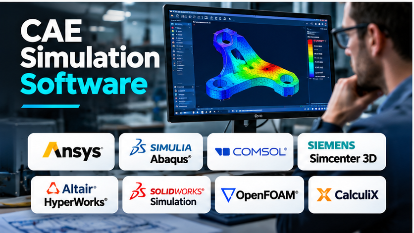
A product can look perfect in a CAD model and still fail when exposed to real-world conditions. A metal bracket may bend under load. An electronic enclosure may overheat. A machine component may experience repeated stress until cracks begin to form.
Finding these problems after manufacturing can lead to costly redesigns, wasted materials, and delayed production.
Computer-Aided Engineering (CAE) simulation software helps engineers study how products and systems may behave before physical production. It uses mathematical models and numerical methods to predict structural, thermal, fluid, motion, and other physical behavior.
However, not every CAE platform solves the same problems. Some specialize in structural analysis. Others focus on multiphysics simulation, fluid dynamics, manufacturing processes, or system-level engineering.
This guide explores the main CAE simulation tools, explains their practical differences, and helps engineering teams choose software that matches their technical requirements.
What Is CAE Simulation Software?
Computer-Aided Engineering software helps engineers analyze, evaluate, and improve designs using computer-based simulations.
Instead of relying only on physical prototypes, engineers can create digital models and apply simulated loads, temperatures, pressures, and operating conditions.
CAE software uses mathematical equations to estimate how a design will respond.
Common applications include:
- Structural analysis: Predicting stress, deformation, and possible failure.
- Thermal analysis: Studying heat transfer and temperature distribution.
- Computational fluid dynamics (CFD): Simulating airflow, liquids, and fluid-related heat transfer.
- Multibody dynamics: Analyzing movement, forces, and mechanical interactions.
- Electromagnetic analysis: Studying electric and magnetic fields.
- Fatigue analysis: Estimating damage caused by repeated loading.
- Manufacturing simulation: Examining processes such as forming, molding, and casting.
CAE supports engineering decisions, but simulation results are not automatically correct. Their accuracy depends on assumptions, material data, numerical methods, and validation against real behavior.
How CAE Simulation Works
A simplified engineering simulation workflow, from geometry to results.
Most CAE projects follow a sequence of connected steps.
1. Prepare the geometry
The engineer creates or imports a CAD model.
Unnecessary details, such as tiny holes or decorative features, may be removed if they do not affect the analysis.
This process is often called geometry simplification or defeaturing.
2. Define materials
The software needs suitable material properties.
For structural analysis, these may include Young’s modulus, Poisson’s ratio, density, and yield strength.
Thermal studies may require conductivity, heat capacity, and thermal expansion data.
Using incorrect material values can produce misleading results.
3. Create the computational model
For many CAE analyses, the geometry is divided into smaller elements or cells through a process called meshing.
The solver uses this discretized model to approximate the physical behavior of the system.
Mesh quality and refinement can strongly influence numerical accuracy.
4. Apply loads and boundary conditions
The engineer defines how the product interacts with its environment.
Examples include applied forces, fixed supports, pressure, temperature, gravity, and contact between components.
Boundary conditions must reflect the intended physical situation.
5. Run the solver
The simulation engine calculates an approximate solution using the selected mathematical model.
The computational effort depends on the problem size, physics, solver settings, and available hardware.
6. Review and validate results
Engineers examine quantities such as stress, displacement, temperature, velocity, or natural frequency.
They should also check numerical convergence, sensitivity to modeling assumptions, and agreement with analytical or experimental evidence.
A visually attractive result plot is not proof that the simulation is reliable.
CAE Simulation Software Platforms Worth Evaluating
The following platforms serve different engineering needs. They are not presented as a universal performance ranking.
1. Ansys Mechanical: Structural and Thermal Simulation
Ansys Mechanical | Structural FEA Analysis Software
How to Perform a Static Structural Analysis in ANSYS
CAE Comparison
Ansys Mechanical is a finite element analysis platform for studying mechanical behavior.
It supports structural analysis, including linear and nonlinear problems, contact interactions, vibration, and thermal-related engineering workflows.
Its capabilities are useful when engineers need to understand how components respond to loads, movement, and temperature.
Where Ansys Mechanical makes sense
It is worth evaluating for mechanical engineering teams working on machinery, industrial equipment, automotive components, and other products requiring detailed structural analysis.
The broader Ansys ecosystem can also support projects involving several types of physics.
Important trade-offs
Advanced analysis requires knowledge of material models, contact behavior, mesh generation, and solver settings.
Licensing and computing requirements can increase with the complexity of the analysis.
Official website: Ansys Mechanical
2. Abaqus: Nonlinear Materials and Complex Structural Behavior
New Seamless SOLIDWORKS Workflow with Proven Advanced Simulation (Abaqus) and Faster Collaboration – Dassault Systèmes blog
Logiciel de simulation – Abaqus/CAE – SIMULIA – de gestion / d’analyse / d’interface
Abaqus怎么导入几何模型 Abaqus怎么处理复杂几何-Abaqus中文网站
Abaqus is a finite element analysis solution within the SIMULIA portfolio.
It is widely associated with nonlinear structural analysis, advanced material behavior, contact problems, and simulations involving large deformation.
Its implicit and explicit solver technologies support different classes of engineering problems.
Where Abaqus makes sense
Abaqus deserves consideration when engineers need to analyze challenging material behavior, complex contact, or highly nonlinear mechanical events.
Examples include rubber components, metal forming, impact, and detailed structural research.
Important trade-offs
Advanced material models and nonlinear analyses require careful calibration and validation.
Solver settings can also have a significant effect on computational cost and convergence.
Official website: SIMULIA Abaqus
3. COMSOL Multiphysics: Coupled Physics Simulation
COMSOL – Software for Multiphysics Simulation
Introduction to Conjugate Heat Transfer Modeling in COMSOL Multiphysics®
Применение мультифизического моделирования при проектировании печатных плат электронных устройств
COMSOL Multiphysics is designed for simulations involving one or more interacting physical processes.
It provides a modeling environment where engineers can combine physics such as heat transfer, structural mechanics, fluid flow, and electromagnetics, depending on licensed modules.
For example, an engineer may study how electrical heating changes the temperature of a component and how thermal expansion affects its mechanical behavior.
Where COMSOL makes sense
COMSOL is especially relevant to research teams, product developers, and engineers working on problems where multiple physical effects interact.
Its equation-based modeling capabilities can also support specialized research applications.
Important trade-offs
The required physics modules can affect licensing costs.
Users must understand the governing equations and coupling assumptions to produce meaningful results.
Official website: COMSOL Multiphysics
4. Siemens Simcenter 3D: Simulation Integrated With Engineering Workflows
Simcenter 3D | Siemens Software
Using Siemens solutions and a small team to develop road-ready vehicle in three years | Siemens
Luggage manufacturer uses Simcenter 3D to design lighter and impact-resistant suitcases | Siemens
Simcenter 3D supports simulation modeling and analysis across multiple engineering disciplines.
Its capabilities include structural dynamics, thermal analysis, and other simulation applications through the broader Simcenter environment.
It can be particularly relevant to organizations that need simulation activities to connect closely with product engineering data.
Where Simcenter 3D makes sense
Simcenter 3D is worth evaluating for engineering teams that work on complex assemblies and want simulation processes integrated with broader design and product development workflows.
Important trade-offs
Available capabilities depend on the chosen products and modules.
Organizations should verify solver requirements, data management integration, and implementation costs before adoption.
Official website: Siemens Simcenter
5. Altair HyperWorks: Simulation Modeling and Optimization
User Interface
Visualize Element Density
Altair Inspire Optimization Workflow
Altair HyperWorks provides tools for simulation model preparation, analysis, and optimization.
The HyperWorks portfolio includes technologies such as HyperMesh for model preparation and OptiStruct for structural analysis and optimization.
These tools are useful for engineers who need to study complex structures or improve designs against defined performance requirements.
Where HyperWorks makes sense
It deserves consideration for organizations working on structural performance, lightweight design, and optimization-driven engineering.
Important trade-offs
The portfolio includes several tools with different purposes.
Teams should identify which components they actually need instead of assuming every capability is included in one license.
Official website: Altair HyperWorks
6. SOLIDWORKS Simulation: Analysis Within a CAD Workflow
SOLIDWORKS Simulation Professional | Visiativ | Visiativ Benelux
Ultrathin SOLIDWORKS Workstations – Benchmarking the Lenovo ThinkPad P16s AMD
SOLIDWORKS Simulation
SOLIDWORKS Simulation provides simulation capabilities within the SOLIDWORKS design environment.
It allows engineers to evaluate mechanical designs without necessarily moving the geometry into a separate specialist application.
Available capabilities vary by product package and may include static, frequency, buckling, thermal, and nonlinear analysis.
Where SOLIDWORKS Simulation makes sense
It is a practical candidate for design teams already using SOLIDWORKS, particularly when simulation is part of routine product development.
Important trade-offs
Teams should verify whether their required physics and solver capabilities are available in their selected edition.
Highly specialized analyses may require a dedicated simulation platform.
Official website: SOLIDWORKS Simulation
7. OpenFOAM: Open-Source Fluid and Multiphysics Simulation
OpenFOAM is an open-source simulation toolkit primarily associated with computational fluid dynamics.
It supports a range of fluid flow and related physical models, making it useful for researchers and engineers who need control over simulation methods.
OpenFOAM is not a direct substitute for a full general-purpose structural CAE suite. Its main strength lies in fluid and related numerical simulations.
Where OpenFOAM makes sense
It is relevant for CFD specialists, research institutions, and technical teams comfortable working with solver configuration and computational workflows.
Important trade-offs
OpenFOAM can require substantial technical expertise.
Users must also plan for meshing, result visualization, computing infrastructure, and ongoing support.
Official website: OpenFOAM
8. CalculiX: Open-Source Structural Finite Element Analysis
CalculiX provides structural finite element analysis capabilities through an open-source software project.
It supports several classes of mechanical analysis and can be used alongside suitable preprocessing and visualization tools.
Where CalculiX makes sense
CalculiX may appeal to researchers, students, and engineering teams seeking an open-source structural solver.
Important trade-offs
Users may need to assemble their own workflow for geometry preparation, meshing, solver input, and result review.
Commercial-style support and integrated user experience should not be assumed.
Official website: CalculiX
CAE Simulation Software Comparison
| Software | Primary specialization | Key advantage | Important consideration |
|---|---|---|---|
| Ansys Mechanical | Structural and thermal FEA | Broad structural analysis capabilities | Licensing and solver expertise |
| Abaqus | Nonlinear structural simulation | Advanced materials, contact, and deformation | Complex modeling requirements |
| COMSOL Multiphysics | Coupled physical phenomena | Flexible multiphysics modeling | Additional modules and physics expertise |
| Simcenter 3D | Integrated engineering simulation | Connection with engineering workflows | Configuration and implementation |
| Altair HyperWorks | Structural analysis and optimization | Meshing and optimization tools | Portfolio and licensing complexity |
| SOLIDWORKS Simulation | CAD-integrated analysis | Convenient design validation | Edition-dependent capabilities |
| OpenFOAM | Fluid dynamics | Open-source solver flexibility | Technical setup and maintenance |
| CalculiX | Structural finite element analysis | Free structural solver | More manual workflow integration |
Understanding the Difference Between Linear and Nonlinear Simulation
One of the most important CAE decisions is whether the physical problem can be represented using a linear model.
Linear analysis
Linear structural analysis generally assumes that material behavior is linear elastic and that deformations are small enough for the governing relationships to remain linear.
For example, a metal bracket carrying a moderate load may be evaluated using a linear static analysis if the assumptions are appropriate.
Linear analysis is often less computationally demanding.
Nonlinear analysis
Nonlinear analysis becomes necessary when the response cannot be represented accurately using linear assumptions.
Common causes include:
- Plastic deformation after a material begins to yield.
- Large changes in geometry.
- Contact between parts that open, close, or slide.
- Rubber and other nonlinear materials.
- Complex loading and instability.
Abaqus and Ansys Mechanical both support nonlinear structural analysis. Their official documentation describes advanced contact, materials, and solver capabilities. Structural FEA Analysis Software+1
The correct approach depends on the physical behavior being modeled, not simply the availability of a more advanced solver.
When Is Multiphysics Simulation Necessary?
Some engineering problems involve several physical processes that influence each other.
Consider an electric motor.
Electrical losses generate heat. Heat changes material temperatures. Thermal expansion can affect clearances and mechanical stress.
A simulation that considers only one physical effect may miss important interactions.
Multiphysics software helps engineers connect these processes.
COMSOL, for example, provides a modeling environment for combining physics through built-in interfaces and user-defined coupling relationships. Understand, Predict, and Optimize
However, coupling additional physics also increases model complexity. Engineers should include interactions that materially affect the engineering decision rather than adding every possible physical effect.
How to Evaluate CAE Software Before Purchasing
A meaningful software evaluation should begin with a representative engineering problem.
For example, a manufacturer could use a loaded mechanical bracket with known material properties and available test results.
The evaluation should examine several areas.
Accuracy and validation
Compare simulation predictions against analytical calculations, published benchmark problems, or physical measurements.
Check whether the differences are acceptable for the intended engineering decision.
Mesh sensitivity
Repeat the analysis using progressively refined meshes.
A useful result should demonstrate appropriate numerical convergence rather than depending heavily on one arbitrary mesh.
Material modeling
Verify that the software supports the required material behavior.
A simple elastic model may be sufficient for one component, while another requires plasticity, creep, fatigue, or temperature-dependent properties.
Solver performance
Measure the time and computing resources needed to complete representative analyses.
Use equivalent assumptions and comparable hardware when comparing products.
Automation and integration
Check whether engineers can reuse models, automate repetitive tasks, and exchange data with existing CAD or product management systems.
Technical support
Ask vendors to help resolve a realistic modeling problem.
The quality of technical support may matter more than a rarely used feature.
The Real Cost of CAE Simulation
CAE software costs can include much more than a license.
Organizations may need additional physics modules, high-performance computing resources, specialist workstations, training, technical support, and validation testing.
The cost of engineering time is particularly important.
An expensive solver that reduces repetitive model preparation may be valuable for a busy engineering department. A smaller team with occasional analysis requirements may benefit more from an integrated CAD simulation tool.
Open-source software can reduce license expenses, but it does not remove the need for qualified engineers, computing resources, and verification.
Common CAE Simulation Mistakes
Trusting colorful result plots without checking assumptions
Stress contours and temperature maps can look convincing even when a model contains serious errors.
Always inspect units, materials, loads, supports, and numerical convergence.
Applying unrealistic boundary conditions
Fixing a component too rigidly can change the predicted stress distribution.
Boundary conditions should reflect how the real product is supported and loaded.
Ignoring mesh quality
Poor elements or inadequate mesh refinement can produce unreliable local results.
Mesh studies are especially important around stress concentrations and other critical regions.
Confusing numerical convergence with physical accuracy
A solver can converge to a mathematically consistent solution for an incorrect physical model.
Validation against suitable evidence remains necessary.
Replacing all physical tests with simulation
Simulation can reduce unnecessary prototypes and guide testing, but it cannot automatically replace required physical verification, certification, or safety testing.
Choosing CAE Software for Different Engineering Teams
| Engineering requirement | Platforms to evaluate |
|---|---|
| General structural and thermal analysis | Ansys Mechanical, Simcenter 3D |
| Complex nonlinear deformation and contact | Abaqus, Ansys Mechanical |
| Coupled thermal, electrical, and mechanical physics | COMSOL Multiphysics |
| Structural optimization and lightweight design | Altair HyperWorks |
| Routine simulation during SOLIDWORKS design | SOLIDWORKS Simulation |
| Open-source fluid simulation | OpenFOAM |
| Open-source structural FEA | CalculiX |
These are starting points for evaluation, not exclusive recommendations.
Frequently Asked Questions
What is the difference between CAD and CAE?
CAD creates and modifies digital designs. CAE evaluates how those designs may behave under specified physical conditions.
Is CAE the same as finite element analysis?
No. Finite element analysis is one important numerical method used in CAE. The broader CAE category also includes CFD, multibody dynamics, electromagnetic simulation, and other engineering methods.
Can CAE software predict product failure?
CAE can help identify potential failure mechanisms and estimate responses under modeled conditions. Reliability depends on accurate material data, assumptions, loading conditions, and validation.
Does CAE software require programming knowledge?
Not always. Many commercial applications provide graphical interfaces. Programming and scripting become more valuable for automation, custom models, and advanced research.
Can small engineering companies benefit from CAE?
Yes. CAD-integrated simulation and selected specialist tools can help smaller companies evaluate designs before manufacturing. The investment should reflect the complexity and frequency of their analysis needs.
Is open-source CAE suitable for professional engineering?
It can be, provided the selected tools support the required physics and the organization has the expertise to verify and validate its analyses. Licensing cost alone does not determine technical suitability.
Building a Reliable Simulation Workflow
The value of CAE software comes from better engineering decisions, not simply faster calculations.
A successful simulation process begins with a clear engineering question. The team then selects suitable physics, creates an appropriate model, checks numerical behavior, and validates the results.
For organizations performing routine structural checks, a CAD-integrated solution may be sufficient.
For complex nonlinear or multiphysics problems, a specialist simulation environment may be justified.
The best platform is the one that helps engineers produce traceable, defensible results while fitting their existing design processes, technical skills, and computing resources.
Reliable simulation depends on both capable software and sound engineering judgment.